VLANs and Trunks
VLANs are an essential part of scalable network design. They allow us to limit a broadcast domain’s size, which can impact performance if a LAN continues to grow uncontrollably. VLANs also allow robust separation of traffic at layer two, which is the basis for role-based security in switched LANs.
Once we create VLANs on one device and need to carry those VLANs to another device, the link between the devices needs to label traffic (frames) with an appropriate VLAN identifier, so the receiving switch knows which VLAN the traffic belongs to. This functionality is enabled when configuring the link between devices (usually switches) a trunk.
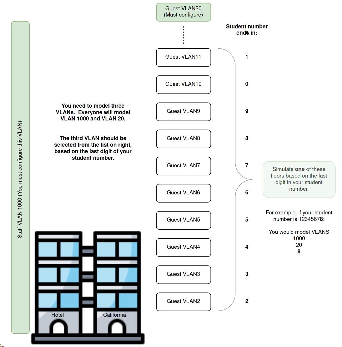
In terms of design, we will manage our broadcast domain’s size by providing one Guest VLAN per floor in our hotel. As we cater to larger Hotels, this policy will give more VLANs in larger hotels and automatically keep the broadcast domain’s size in check. This approach means that the hotel will not provide guests with protection from one another using VLANs. The VLANs are purely there to manage broadcasts, and a guest will be in a particular VLAN depending solely on what floor they are occupying.
Staff working in the hotel are provided with a separate VLAN to isolate them from the guests. This is an example of role-based security. We will implement more security when we cover access control lists (ACL) later in the case study. There is just one VLAN for staff, and this applies, regardless of the floor on which the staff member works.
As this is a model, we won’t implement every floor. We will model the Staff VLAN and two of the guest VLANs as outlined in the diagram below:
What you need to do?
- You should create and name one VLAN for hotel staff (VLAN_ID 1000) and a separate VLAN for Guests on level 20 (VLAN_ID 20), and another VLAN as selected from the image above. Thus you will model three VLANs at each site.
- You should configure trunks between the access and distribution layer devices.
- You should place the access layer ports used by the PCs in appropriate VLANs.
- Guest1’s switch port should be in VLAN20
- Apply the following command switchport access vlan 20.
- Best practice is to be sure that switchports that face the edge of the network (where users are) are locked to one particular VLAN and does not form a trunk (carries all VLANs) which some switches can negotiate. Apply the following command switchport mode access to all switch ports connected to PCs.
- Guest2’s switch port should be placed in the VLAN selected using your student number.
- Also, remember to lock the port to “mode access”.
- Place all the ports connected to staff PCs in VLAN 1000.
- Again, lock their port to “mode access”. Just because they are staff doesn’t give them the right to access every VLAN.
- Guest1’s switch port should be in VLAN20
Where to configure this?
VLANs define the security roles for devices at the access layer. The VLANs provide a separation of traffic that forms the basis of security at this layer. To provide connectivity between VLANs we need routing, and the distribution layer delivers that function. Thus the VLANs need to be present on that layer as well. Our links need to be configured as trunks to carry VLAN information (tags) between the access and the distribution layer.
Every access layer and distribution layer device that deals with a particular VLAN needs to have that VLAN present, and every link between the two layers needs to be a trunk. The VLAN and trunks will often need to cover more links than are necessary for bare connectivity because we are also providing redundant paths for reliability.
*Hint - The distribution layer and the access layer need the same VLAN configuration. Conveniently, the interfaces between the access and distribution layers have the same numbering (luck), and they all need to be trunks. In other words, the trunk and VLAN configuration on every switch are identical! Spend your time making sure those commands are correct. Then - notepad, copy and paste are your friends. Adding more floors or more hotels is easy - this is a scalable design.
The only difference between the access layer and the distribution layer is the presence of the PCs. So you will need a separate step to configure the ports connected to the PCs. Some of the PC’s between AL1 and AL2 are on different floors so take care with copying and pasting.
How will you know it is configured correctly?
You can use the show vlan and show interfaces trunk commands to verify VLAN and trunk creation and the assignment of ports (interfaces) to VLANs. You can assign some temporary IP addresses to the hosts and verify that all hosts within a VLAN can ping each other. Hosts in different VLANs should not be able to ping one-another even if they are in the same VLAN.
Example output from PERAL2’s perspective. Note that the Access layer should show the ports you placed in a VLAN listed alongside the VLAN. If you perform the same command on the Distribution layer, you will not see specific ports associated with a VLAN. This is because all the ports on the distribution are trunks. They can carry (tag) any VLAN traffic, but they themselves are not associated with a single VLAN.
PERAL2#sh vlan

VLAN Name                             Status    Ports
---- -------------------------------- --------- -------------------------------
1    default                          active    Et0/2, Et0/3
20   Level20                          active
25   Level25_Yours_will_be_different  active    Et0/0
1000 Staff                            active    Et0/1
1002 fddi-default                     act/unsup
1003 token-ring-default               act/unsup
1004 fddinet-default                  act/unsup
1005 trnet-default                    act/unsup

VLAN Type  SAID       MTU   Parent RingNo BridgeNo Stp  BrdgMode Trans1 Trans2
---- ----- ---------- ----- ------ ------ -------- ---- -------- ------ ------
1    enet  100001     1500  -      -      -        -    -        0      0
20   enet  100020     1500  -      -      -        -    -        0      0
25   enet  100025     1500  -      -      -        -    -        0      0
1000 enet  101000     1500  -      -      -        -    -        0      0
1002 fddi  101002     1500  -      -      -        -    -        0      0
1003 tr    101003     1500  -      -      -        -    -        0      0
1004 fdnet 101004     1500  -      -      -        ieee -        0      0
1005 trnet 101005     1500  -      -      -        ibm  -        0      0

Remote SPAN VLANs
------------------------------------------------------------------------------


Primary Secondary Type              Ports
------- --------- ----------------- ------------------------------------------
PERAL2#sh interfaces trunk

Port        Mode             Encapsulation  Status        Native vlan
Et1/0       on               802.1q         trunking      1
Et1/1       on               802.1q         trunking      1
Et1/2       on               802.1q         trunking      1
Et1/3       on               802.1q         trunking      1

Port        Vlans allowed on trunk
Et1/0       1-4094
Et1/1       1-4094
Et1/2       1-4094
Et1/3       1-4094

Port        Vlans allowed and active in management domain
Et1/0       1,20,25,1000
Et1/1       1,20,25,1000
Et1/2       1,20,25,1000
Et1/3       1,20,25,1000

Port        Vlans in spanning tree forwarding state and not pruned
Et1/0       1,20,25,1000
Et1/1       1,20,25,1000
Et1/2       1,20,25,1000

Port        Vlans in spanning tree forwarding state and not pruned
Et1/3       none
PERAL2#
What questions could you see on the practical exam?
You might need to assign a port to a new VLAN, simulating an individual or device’s reassignment to a new location.
- There could be a fault in the network caused by a user being in the incorrect VLAN.
- There could be a fault in the network caused by a link not being a trunk.
- There could be a fault in the network caused by a VLAN not being present on a switch.