STP Default Behavior
Overview
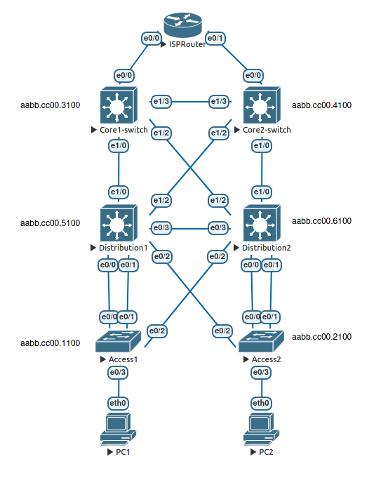
Six switches have just been installed in a classic redundant three-layer hierarchy. The access layer is depicted as layer 2 switches and the core and distribution as layer 3 switches (combined switch/router) as this is the most common practice. However, in this lab we are not enabling routing (layer 3) on the distribution or core switches and you can consider the entire network as layer 2 only. There are many redundant links between the layers. Because of the possibility of bridging loops, spanning tree logically removes any redundant links. In this lab, you will observe what Spanning Tree does and why.
Note: There may be small variations in the MAC addresses seen in EVE and in this documentation. MAC addresses are tied to the physical equipment and this is emulated by EVE. As a consequence different versions of EVE-NG may assign different MAC to the device.
Learning Objectives
At the end of this lab you should be able to:
- Explain the purpose of STP.
- Determine the STP structure of an Ethernet switched network using the Cisco IOS commandline.
Topology
About the Spanning Tree Protocol and Ethernet switches.
As Spanning Tree is a layer 2 protocol, it operates without the need for any network layer (IP) addressing. Switches forward Ethernet frames based purely on the frame’s destination MAC addresss and the local switch’s knowledge (if any) of which port that MAC is associated with. Most switches ship with the Spanning Tree Protocol (STP) enabled by default. Unlike routers, switches normally ship with all of their ports enabled (no shutdown). As a consequence of ports being enabled and the self learning of MAC addresses, a switch can be used “straight out of the box” and it will provide basic connectivity.
That is the state in which you find the switches in this topology. They are in their default configuration apart from the setting of hostnames which has already been performed.
Recall that after the switches are powered up, spanning tree is initiated, and the switch detects the redundant links. By default, spanning tree runs on every port. When a new link becomes active, the port goes through the IEEE 802.1D spanning tree listening and learning states before transitioning to the forwarding state. During this period, the switch discovers if it is connected to another switch or an end-user device. One of the switches is elected as the root bridge for the tree. Then each switch independently determines which links to keep active and which links to logically remove from the spanning tree (block) if multiple links exist.
What type of frame does STP use to communicate with other switches?
Default behaviour
Display default spanning tree information for all switches
*Verify IEEE 802.1D STP status with the show spanning-tree command on Distribution1.
Distribution1#show spanning-tree

VLAN0001
  Spanning tree enabled protocol ieee
  Root ID    Priority    32769
             Address     aabb.cc00.1000
             Cost        100
             Port        1 (Ethernet0/0)
             Hello Time   2 sec  Max Age 20 sec  Forward Delay 15 sec

  Bridge ID  Priority    32769  (priority 32768 sys-id-ext 1)
             Address     aabb.cc00.5000
             Hello Time   2 sec  Max Age 20 sec  Forward Delay 15 sec
             Aging Time  15  sec

Interface           Role Sts Cost      Prio.Nbr Type
------------------- ---- --- --------- -------- --------------------------------
Et0/0               Root FWD 100       128.1    P2p
Et0/1               Altn BLK 100       128.2    P2p
Et0/2               Desg FWD 100       128.3    P2p
Et0/3               Desg FWD 100       128.4    P2p
Et1/0               Desg FWD 100       128.5    P2p
Et1/1               Desg FWD 100       128.6    P2p
Et1/2               Desg FWD 100       128.7    P2p
Et1/3               Desg FWD 100       128.8    P2p


Distribution1#
Notice that some of the ports are blocking BLK. These ports will not pass regular frames or broadcasts and thus break any switching loops that are present. It is important to note that a blocked port can receive BPDUs. In fact, it is the BPDUs that keep a port in the blocked state.
-
If you have a paper copy of the topology, mark the blocked ports for the Distribution1 switch.
-
Repeat the “show spanning-tree” command on each of the switches and record the blocked ports on your topology diagram.
-
Label the root-bridge (root switch) in your topology.
-
Once you have labelled your diagram, verify that the resulting topology is in fact loop free. It is worth taking the time to work through the spanning-tree decision process to see if you can explain how the blocked ports are determined.
After reviewing the spanning tree output, Make sure you are able to answer the following questions:
Which switch is the root of the spanning tree?
__________________________________
How can the root switch be identified?
__________________________________
Why was that switch selected as the root?
__________________________________
What caused one port to be in blocking state over another?
__________________________________
Another useful STP command is show spanning-tree root. This command displays a summary listing of the VLANs defined, the Root (bridge) ID for each one, the Root Cost and the Root Port that the switch uses to reach the root bridge. In this lab the only active VLAN is default VLAN 1. Issue the show spanning-tree root command on each of your switches.
Access1#show spanning-tree root

                                        Root    Hello Max Fwd
Vlan                   Root ID          Cost    Time  Age Dly  Root Port
---------------- -------------------- --------- ----- --- ---  ------------
VLAN0001         32769 aabb.cc00.1000         0    2   20  15
Access1#
Summary
In this lab, the default operation of IEEE 802.1D spanning tree was observed. Since no bridge priorities were specified, the switch with the lowest MAC address was elected as the root. The link providing the lowest root path cost was chosen as the active link. If costs were equal, the tie was broken first by the lowest sender BID of the BPDU, then by the lowest sending port priority and last by the lowest sending port number. In the next lab, the default STP behavior will be modified so that spanning tree works according to specifications.
Exercise
This is worth doing - There is invariably an exam question that will require you to identify the spanning tree port states for a topology given only the MAC addresses and link speeds.
Given the initial topology in this lab, and the actual MAC addresses present. Determine how your Spanning Tree topology would look if you completely removed the current root switch.
- Start by determining the new root bridge based on the MAC address.
- Record the spanning tree costs for each link.
- Determine the root ports based on cost.
- Tie breaker is the Lowest sender BID or if the BIDs are equal, the Lowest port ID.
Check your calculations
- Power down your existing root switch or shut down all the ports on your current root switch.
- Compare your calculated topology with the observed behaviour of the physical switches.