Multiple Spanning Tree
Overview
Cisco’s Per VLAN Spanning Tree (PVST) provides a significant step up from the standard spanning tree in terms of flexibility, allowing each VLAN to have its own independent spanning tree, thereby make better use of available links in the network. A drawback to PVST is an instance of PVST running for EVERY VLAN in the network, regardless of whether different spanning-tree topologies are required. This presents the potential for overwhelming the switch CPU and memory. Additionally, some Cisco switches allow only a limited number of PVST instances – usually 128. If more than 128 VLANs are created, some will not have any STP running, and therefore not have any switching loop protection. PVST and Rapid PVST are simply unusable in that kind of environment. Lastly, PVST and Rapid PVST are Cisco-proprietary protocols that adds complexity in mixed vendor environments.
MST is an open protocol and builds on Rapid Spanning Tree (RSTP), sharing all its rapid convergence properties, and in fact, the only standardized spanning-tree protocol for VLAN-based networks supported by multiple vendors. It is important to note that when MST (multiple) is selected, RSTP (Rapid) will also be present.
MST is a compromise between common spanning-tree (one tree serving all VLANs) and per-VLAN spanning tree. An MST instance represents a unique spanning-tree topology that can support any VLANs the administrator chooses.. Multiple MST instances can be created to account for each of the required spanning-tree topologies in a network, and an arbitrary number of VLANs can be mapped to a single MST instance.
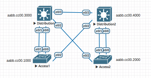
In this lab, you will set up two instances of MST, one for each DL Switch. You need to map appropriate VLANs to the MST instance to ensure that traffic takes the most efficient path from the host to its default gateway. IE one MST instance should have the root bridge set as Distribution1, and the other instance should be set as Distribution2. A VLAN whose hosts use Distribution1 as a gateway should be mapped to the first instance. In contrast, a VLAN whose hosts use Distribution2 as a gateway should be mapped to the second instance.
Learning Objectives
At the end of this lab you should be able to:
- Observe that conventional Spanning Tree is very slow to converge
- Implement Multiple Spanning Tree
- Observe that when implementing MST, RSTP (Rapid) is also included and convergence is faster.
Topology
Steps
Step 1 - Observe that 802.1D and Cisco PVST are slow
- Observe the spanning tree port states on Distribution2 using the show spanning-tree command.
Distribution2#show spanning-tree

VLAN0001
  Spanning tree enabled protocol ieee
  Root ID    Priority    32769
             Address     aabb.cc00.1000
             Cost        100
             Port        3 (Ethernet0/2)
             Hello Time   2 sec  Max Age 20 sec  Forward Delay 15 sec

  Bridge ID  Priority    32769  (priority 32768 sys-id-ext 1)
             Address     aabb.cc00.4000
             Hello Time   2 sec  Max Age 20 sec  Forward Delay 15 sec
             Aging Time  15  sec

Interface           Role Sts Cost      Prio.Nbr Type
------------------- ---- --- --------- -------- --------------------------------
Et0/0               Desg FWD 100       128.1    P2p
Et0/1               Desg FWD 100       128.2    P2p
Et0/2               Root FWD 100       128.3    P2p
Et0/3               Altn BLK 100       128.4    P2p

Distribution2#
Notice that the spanning-tree type is ieee which means legacy 802.1D STP. Notice that the root port for this switch is Et0/2. This is the lowest cost path to Access1 which is the STP root bridge. Also notice that Et0/3 forms a loop and STP is blocking that port.
Let’s simulate the failure of the Root port and see how long STP takes to recover from the fault.
You need to do this sequence quickly and the first time you may be too slow. So repeat the exercise and seek assistance from your instructor if you have trouble seeing what is happening.
- Shutdown Et0/2 and then immediately perform a show spanning-tree and keep repeating (use up-arrow) the command to watch Spanning Tree cycle through the STP states.
Distribution2#conf t
Enter configuration commands, one per line.  End with CNTL/Z.
Distribution2(config)#interface e0/2
Distribution2(config-if)#shutdown
Distribution2#show spanning-tree

VLAN0001
  Spanning tree enabled protocol ieee
  Root ID    Priority    32769
             Address     aabb.cc00.1000
             Cost        200
             Port        4 (Ethernet0/3)
             Hello Time   2 sec  Max Age 20 sec  Forward Delay 15 sec

  Bridge ID  Priority    32769  (priority 32768 sys-id-ext 1)
             Address     aabb.cc00.4000
             Hello Time   2 sec  Max Age 20 sec  Forward Delay 15 sec
             Aging Time  300 sec

Interface           Role Sts Cost      Prio.Nbr Type
------------------- ---- --- --------- -------- --------------------------------
Et0/0               Desg FWD 100       128.1    P2p
Et0/1               Desg FWD 100       128.2    P2p
Et0/3               Root LIS 100       128.4    P2p


Distribution2#
In the output above you can see that Et0/3 has changed to the LISten state in preparation for taking over as the root port.
- If you keep executing show spanning-tree you will see the port transition to LRN (learn) and ultimately forwarding (FWD). Until the port moves to the FWD state, Distribution2 is isolated from the root switch and connectivity is not complete.
You should find that the above process takes around 30 seconds.
- Restore the operation of Et0/2
Distribution2(config)#interface e 0/2
Distribution2(config-if)#no shutdown
Step 2 - Implement Multiple Spanning Tree (MST)
We will now implement MST. Keep in mind that this will give us more than one spanning-tree (MST) and also activate Rapid Spanning Tree (RSTP) so the network should recover from failure more quickly.
- Issue the global configuration command spanning-tree mode mst on all of your switches.
An example from Distribution1:
Distribution1#configure terminal
Enter configuration commands, one per line.  End with CNTL/Z.
Distribution1(config)#spanning-tree mode mst
Distribution1(config)#exit
- Now perform a show spanning-tree on Distribution1.
Distribution1#show spanning-tree

MST0
  Spanning tree enabled protocol mstp
  Root ID    Priority    32768
             Address     aabb.cc00.1000
             Cost        0
             Port        1 (Ethernet0/0)
             Hello Time   2 sec  Max Age 20 sec  Forward Delay 15 sec

  Bridge ID  Priority    32768  (priority 32768 sys-id-ext 0)
             Address     aabb.cc00.3000
             Hello Time   2 sec  Max Age 20 sec  Forward Delay 15 sec

Interface           Role Sts Cost      Prio.Nbr Type
------------------- ---- --- --------- -------- --------------------------------
Et0/0               Root FWD 2000000   128.1    P2p
Et0/1               Altn BLK 2000000   128.2    P2p
Et0/2               Desg FWD 2000000   128.3    P2p
Et0/3               Desg LRN 2000000   128.4    P2p
-
Notice that the spanning-tree protocol is now mstp
-
Repeat the earlier exercise where you shutdown the root port and repeatedly show spanning-tree.
You should find that the a new root port is almost immediately brought to forwarding FWD. You should also see that RSTP doesn’t go through a listening state but rather goes directly to LRN (learning) which improves the convergence time.
- At the end of this exercise be sure to perform a no shutdown to restore full conectivity.
i
Step 3 - Observe default MST configuration
At this point, MST is running with default parameters. On any switch, issue the command show spanning-tree mst configuration to see the configuration information:
Distribution2#show spanning-tree mst configuration
Name      []
Revision  0     Instances configured 1

Instance  Vlans mapped
--------  ---------------------------------------------------------------------
0         1-4094
-------------------------------------------------------------------------------
Distribution2#
The output tells us:
- The region is un-named
- The revision number is 0
- There is one instance of MST, number 0, and all VLANS 1-4094 are mapped to that instance.
For MST to work, the region must be named and given a revision number (it is just an administrator-assigned value). All the switches in the same region must have the same region name and revision number, and have the same VLAN-to-instance mapping.
Step 4 - Create VLANs and trunks
We have multiple spanning trees so that different VLANs can have their own tree that is optimised for their purpose and configuration.
We need VLANs and we need trunks between switches to carry VLAN traffic. To save time the commands below can be copied and pasted onto each of your switches. This will turn trunking on all interfaces and creat four VLANs. The “vtp mode off’ is necessary so that EVE can capture VLAN configuration if you export it. Always include this commend in EVE when configuring switches.
- Copy the commands below to each of your switches:
enable
conf t
vlan 10
name Accounts Level 1
vlan 20
name Accounts Level 2
vlan 30
name Sales Level 1
vlan 40
name Sales Level 2
vtp mode off
interface range Ethernet 0/0-3
switchport trunk encapsulation dot1q
switchport mode trunk
exit
Step 5 - Manually Configure MST
- Now configure MST on all switches with the following information (you must configure each switch manually):
Region Name: CCNP
Revision Number: 1
VLAN Mappings: Instance 1: Accounts, Instance 2: Sales.
MST region configuration is performed in a special mode under the global configuration that is entered using the spanning-tree mst configuration command. You have to make the changes and exit from configuration mode to have the changes applied; the changes are not applied until you exit. While in MST configuration mode, you can use the show current and show pending commands to see how the configuration stands.
It is strongly recommended that you copy the relevant commands into an editor and then paste them into each switch.
Distribution1#conf t
Enter configuration commands, one per line.  End with CNTL/Z.
Distribution1(config)#spanning-tree mst configuration
Distribution1(config-mst)#name CCNP
Distribution1(config-mst)#revision 1
Distribution1(config-mst)#instance 1 vlan 10, 20
Distribution1(config-mst)#instance 2 vlan 30, 40
Distribution1(config-mst)#exit

Distribution1#show spanning-tree mst configuration
Name      [CCNP]
Revision  1     Instances configured 3

Instance  Vlans mapped
--------  ---------------------------------------------------------------------
0         1-9,11-19,21-29,31-39,41-4094
1         10,20
2         30,40
-------------------------------------------------------------------------------
Distribution1#
Notice that we have three spanning-trees, the default (instance 0) that all VLANs automatically use and the two we manually mapped (instance 1 and 2). We have assigned Accounts VLANs to instance 1 and Sales VLANs to instance 2.
- Issue the show spanning-tree mst command:
Distribution2#show spanning-tree mst
*2024 Note - Terry had to repeatedly issue this command to get the output to fully dispay. It did after several goes. If it seems to truncate/hang, press
-
Notice that STP now reports the three instances and the state of the ports will be identical* for each instance. At this stage all three spanning-trees are the same so there isn’t much point having them.
-
Instance 0 will have more ports active because there are some interfaces in VLAN1 that do not carry the other VLANs (they are not trunks).
Step 6 - Manipulate the spanning tree
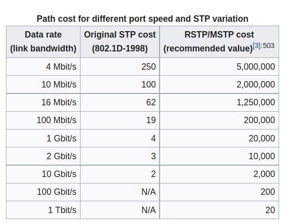
To this point we have left election of the root bridge up to the protocol defaults, which are the same as PVST with one exception – port cost values, still based on the physical interface’s bandwidth, use much larger numbers.
An example of the show spanning-tree root command at Distribution2 provides proof that the root bridge is elsewhere:
Distribution1#show spanning-tree root

                                        Root    Hello Max Fwd
MST Instance           Root ID          Cost    Time  Age Dly  Root Port
---------------- -------------------- --------- ----- --- ---  ------------
MST0             32768 aabb.cc00.1000         0    2   20  15  Et0/0
MST1             32769 aabb.cc00.1000   2000000    2   20  15  Et0/0
MST2             32770 aabb.cc00.1000   2000000    2   20  15  Et0/0
Distribution1#
Port costs, which are summed to find a path cost in the quest for a root bridge, are different in MST:
 (https://en.wikipedia.org/wiki/Spanning_Tree_Protocol - August 2022)
MST uses the same basic commands and values to manipulate it’s operation.
To manually configure a bridge to be the primary MST root, use the command spanning-tree mst instance-list root {primary!secondary} global configuration command. You can also manually set the bridge priority using the spanning-tree mst instance-list priority priority global configuration command. In the example below, Distribution1 is configured as the primary root for instance 0 and 1, and the secondary root for instance 2:
Distribution1# conf t
Enter configuration commands, one per line.  End with CNTL/Z.
Distribution1(config)# spanning-tree mst 1 root primary
Distribution1(config)# spanning-tree mst 2 root secondary
Distribution1(config)# end
Distribution1#
Distribution2 is configured with a complementary set of instructions; root primary for instance 1 and root secondary for instance 0:
Distribution2# conf t
Enter configuration commands, one per line.  End with CNTL/Z.
Distribution2(config)# spanning-tree mst 1 root secondary
Distribution2(config)# spanning-tree mst 2 root primary
Distribution2(config)# end
Distribution2#
The results of these configuration changes are evident using the show spanning-tree root command. From Access1, you can see that the root ID now corresponds to Distribution1 and Distribution2 for instances 1 and 2. In other words we have two independent trees and you will find that some ports will block for one VLAN and forward for another. This helps to make use of the available bandwidth.
Access1#show spanning-tree root
                                        Root    Hello Max Fwd
MST Instance           Root ID          Cost    Time  Age Dly  Root Port
---------------- -------------------- --------- ----- --- ---  ------------
MST0             32768 aabb.cc00.1000         0    2   20  15
MST1             24577 aabb.cc00.3000   2000000    2   20  15  Et0/0
MST2             24578 aabb.cc00.4000   2000000    2   20  15  Et0/2
Access1#
Step 7 - Confirming that there are two independent Spanning Trees
- Using the show spanning-tree mst command, confirm that the two instances have separate Spanning Trees that support efficient paths to the STP root on Distribution 1 or Distribution 2.
Best practice will be to align the default gateway with spanning tree. So if Distribution 1 is the STP root for VLAN 10 its router should also be the default gateway for that VLAN.